Saturday, February 13, 2016

How to set valve lash, part 2


Physical inspection:

I got back into the cold garage today. The camera still did not work, so I will describe what I observed. I took the intake manifold off so I could easily see when the lifters moved. My damper has marks at 0, 90, 180, and 270 degrees (it is also fully degreed for probably the first 50 degrees BTDC) so my readings are very close estimates from these marks.
Using my great motor turning tool, I brought the #1 cylinder up to compression stroke TDC (0 degrees). I then rotated the motor through 2 full crankshaft rotations as a 4-stroke motor requires. This will be 720 degrees in total. The camshaft will only turn 1 revolution during the same time.

After turning about 90 degrees, the exhaust valve lifter begins to move upward. It moves up and then back down, resting on the base circle at about 360 degrees.

The intake valve lifter also moves upward just before this time. It moves up and then back down, resting on the base circle at about 630 degrees.


The motor now has 90 more degrees before compression TDC.

So our observations match our expectations. Both lifters are on the cam base circle for about 180 degrees during the compression, spark, and power events. Plenty of time to set lash!


Your comments are welcome.

Friday, February 12, 2016

How to set valve lash.


Introduction:


I regret that Hot Rods in the Hudson Valley is a bit of a dead link, so I thought I would at least leave something helpful on here as my legacy:

The Premise:

Over the years I have heard some extremely complicated methods about how to set lifter lash. But does it really have to be that complicated?

The very simple method I have used for years is as follows:

1.    We will be working on the #1 cylinder. Each piston will be at TDC twice in a four stroke motor. We want to find the TDC where compression is occurring. Put a breaker bar on the damper bolt, and bring the motor around to just before 0 degrees on the damper. Put your thumb (or someone else’s thumb) over the open spark plug hole as you are doing this. If you feel air trying to push out, this is the compression stroke.*  The compression stroke is what we want. *Please do not put anything INTO the cylinder. You could quickly lose a finger-tip I am serious.

2.    Loosen (or install) the rockers on cylinder #1. I spin the pushrods between your fingers, one at a time, while tightening the rocker, until the pushrod has some resistance to turning easily. Then turn the rocker adjusting nut ½ turn more, and then tighten the locknut fully.

3.    Turn the motor in 90 degrees increments, each time repeating the process for the next cylinder in the firing-order. The Chevy firing order is one of the few things I have memorized years ago.

This has seemed to work acceptably for as long as I have done it. But few I people will accept it. I guess it’s too simple to be right. It just has to be a complicated, 50-step procedure to be right, right?

I decided to find out what my method does, both by thinking logically about it, and then directly inspecting what actually happens in a motor.

Inspection of available data:
Now I know that the lifter has to be on the cam base circle when the lash is set, it cannot be on the lobe ramp. This makes sense to me; the base circle is a known dimension. The ramps will cause the lifter height to vary. This seems intuitive enough that I get it. So I want to find a cam position when both lifters will be on the base circle!


The above cam-lift graph illustrates what is a typical cam is doing. We will read the graph (in a very simplified fashion) from left to right. Note that the -360 line and the 360 line are the same line; the cycle repeats over and over. Hopefully.

Moving left to right; the red curve is where the exhaust valve is working. Then the blue curve is where the intake is working (Yes, there is a short time where they are both open, this does not concern us).

So on the ends of the graph, from about 270 to 360 on the right, and -360 to -270 on the left, both valves are closed. Of course they are closed; this is when compression, spark, and the power event are happening! Use some logic, how could these happen with the valves not fully closed? Ok, so we have established almost 180 continuous degrees where the valves are closed.


A second inspection of data:


The above illustration is a representation of the end view of a physical pair of cam lobes that would control the lifters in a cylinder. Again, this cam will rotate 1 revolution clockwise in the time the piston has traveled up and down 2 times.

Visualize a second lifter behind the one shown.

As the cam rotates, the exhaust lifter will come down to the base circle. Around that time, the intake lifter will go up and back down on the (blue) intake cam lobe. Notice the period after that, during D and A. The valves are both fully closed! Of course they are, look at the notation for D. Compression is just beginning.

Now by looking at this illustration, I estimate a way more conservative 90 degrees of both valves being closed. It bothers me a little that I don’t know how to reconcile the 90 degree difference between the 2 graphs, but even using just 90 degrees, that’s a lot.

Now right in the middle of that time; both valves closed, compression stroke, TDC, is when I am doing my lifter adjustment.

Do you think my method could be out more than 45 degrees in either direction? I don’t.


Objections:

I will now address some objections you might raise:

1.    That’s a wimpy cam chart. What about a super-duper, ultra-high-lift, I’m-a-real-man, drag racing cam?

Go ahead and look up the biggest racing roller cam chart and check it. There will still be plenty of degrees where both valves are closed. A compression motor kind of relies on it. Do you know a motor where the valves are open during compression, spark, and power? Does this motor run?

2.    What about spark advance? Motors don’t spark at TDC, they spark way before TDC.

It is true that the spark event should occur earlier than compression TDC. The cylinder explosion takes time to fully happen, and yes, it must be triggered earlier as engine speed increases, since it takes about the same time to occur. But the spark event is completely independent of lifter adjustment. Think about it; everything we have discussed so far is damper degrees, cam degrees, lobes, etc. The cam is physically connected to the crank (and thus the damper) by the timing chain. This relationship is never changed. Spark should occur at an optimum time, but you could change it to any time and it will not affect the damper to cam to lifter relationship. It just can’t. Don’t be confused about this.

3.    Well you’re describing adjusting hydraulic cam lifters; this is not the same as adjusting solid or roller cam lifters.

This is just an extension of the first objection. The physical steps performed during step 2 above will be more complex for adjusting solid and roller cams (if you have one, you already know this). This is because instead of eliminating excess play (or lash) as described for hydraulic, for solid or roller cams one must actually make sure that a measured and controlled looseness (or clearance) is present. I did not feel the need to explain that level of complication to those that don’t know about it, since again, it just doesn’t matter! All cams will have the lifters on the base circle during compression, spark, and power events.

4.    I have my cam advanced/retarded, so my TDC is different than yours.

Really? That’s great. Do you have it advanced or retarded more than 22 degrees? (see Physical inspection below) I don’t think so.


Physical inspection of a motor:

I spent a very cold afternoon today huddled over my big block in the garage doing some real-world examination. The motor is out, on a stand. I recently changed intake manifolds, and I was going to take the manifold back off to do my verification. The coldness being what it was, I just left it on and decided I could watch the upper ends of the pushrods just as easily to see lifter movement. I set up a dial-indicator to measure lifter movement. I ran the damper around plenty of times, carefully watching the lifter movement periods.

I didn’t take any photos since they would just be static photos showing the positions of things and would not be real exciting. Plus it was really cold.

The lack of pushrod movement confirmed my ideas about the lifters being on the base circle during TDC. There was an estimated 45 degree dwell time where the lifters just don’t move. I don’t know the reason for the reduction in base circle degree dwell time again, but I think my premise is still valid. I could not be off by 22 degrees in either direction.


Future plans:

This spring I will get a degree wheel on there, and my dial indicator in place, and do a full 720 degree study of both lifters on cylinder #1, complete with exciting photos.


Your comments are welcome.


Sunday, June 22, 2014

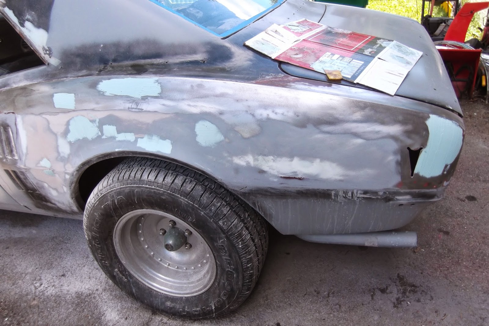
Drivers side quarter panel needed lots more work.

The bodywork tune-up is finding and fixing EVERY little problem before final paint. I shot most of the car in primer, and many of the problems quickly became evident. The drivers side quarter panel is a good example.
 
 I shot a light coat of black paint over the gray primer (the black is called the guide coat) and sanded away. I have to eliminate the 'orange peel', or unevenness of the primer coat and get it dead flat. Any black area left over are low spots that have to be looked at.


I found some badness in this area, so I had to redo some filler work.


It was also clear that the old paint on the top areas had to be stripped off. There was cracking showing through the primer.


Here we have more of the paint stripping done. Some old filler came out so I had to redo that too.


Here are just a few areas that got new filler. There were at least this many more that had to be done after these spots.


Here we have some of the new filler all sanded out and blended in.


 Final work on this area in front of the rear tire. Its all fixed now. I am still going to have to get those chrome "vent" trim pieces off and detail that area.


More blending in of the new filler. Thats all new steel in the fender lip area.


Heres about where we are behind the tire. This area is pretty close. I have to get another coat of primer on it and do another sanding.

Monday, June 16, 2014

One panel DONE

 
I am starting a new job soon so I am taking some time off to concentrate on the Firebird full time. My goal is to get one panel per day "done". This means all filler done, all scratches out, and in primer, ready for final sanding. I am approaching this one panel at a time for a couple of reasons. First, is so doing the whole car doesnt seem so overwhelming. Second, is so I can give each panel the detailled attention needed to do a good job. Third, this makes definite, achieveable goals that I can accomplish and feel good about.
 
 
The existing paint on the above fender had very heavy cracking on the top areas, probably from sun exposure over the years. When I was younger, I had a car painted by somebody, and they painted over similar cracking. It looked great at first, but as the paint continued to dry, it sat down in the cracks and looked like hell. So I know the cracks have to come out. I could sand them out or strip the paint, I chose to strip it. Sanding would require a pretty coarse grit, and then if I don't get all the scratches out, it's just as bad as the cracking. Stripping takes a lot of time, but it's not difficult.


Here is the fender after wet-sanding. This gets all the remaining paint and primer level. At this point you have to go over the entire panel, feeling every tiny bit by hand, feeling for any bad spots. I am not kidding when I say you have to try to find every little bloop. The tiniest imperfection will stand out in new paint, and then it's too late. The only way to do it is by feeling.


I had to fill a lot of small chipped areas with a skim coat of filler. There were a lot of chips on the panel behind the tire (naturally). Once all the filler is done, all chips filled, all sanding scratches sanded out, all paint edges feathered, everything feeling flat, it's ready for primer. I call that the tune-up phase. This stage looks simple, but it is critical. This is the second to last chance to get it all really right. You can't ignore any problems you find here. Then the entire panel gets shot in primer. After the primer dries, I will give it a final sanding before paint. At that point it has to be perfect.

Saturday, September 21, 2013

The Doors

Here is typical work needed to repair the rustouts in a door. Here is one outside corner. First I made a cardboard template that defines the door edges, so that after I cut the rust off, I can have some idea of where the door edges were. Basically the whole corner of the door gets cut off. I apply POR-15 rust converter to every inside surface I can. This stops the rusting process by chemical conversion.
Here is the new outer patch welded in place. I had to form the body lines, the drop crease, by hand. This will get filler to finish it off.
Above is the other lower corner of the same door. Same process: make a template, cut out the rust, POR-15 the inside, form a new patch, weld it in.
And it looks like this.
This was a little hiccup. I had the 2 lower corner patches in place, so I rehung the door on the car to check the fit. Unfortunately, despite my template, the edge near the door wasnt right, it was too long. I marked it with a marker to show how much had to be trimmed. Off comes the door again, and I trimmed the door and remade the edge. This is why we trial fit things, if I had found this out later, it would have been even worse to fix.
Above is one inside lower corner after patching. I even put strips of metal along the edges to replicate the folded over part of the outer door skin. Looks factory.
After filler and sanding. You can see the "folded edges" I made.


Here is the other inside corner after patching. WHOA! (I dont know why I dont have 'before' photos for these, sometimes I get so caught up I forget). Anyway, I have to make each individual piece, make sure it is the right shape, angle, and curve, and then tack weld it all together. This was a lot of work, but like all things that are a lot of work, it was very satisfying.
Same area after grinding. I have the 'folded edges' tacked in. Still have to seam weld the edge and finish grind it.


After filler and sanding. Came out perfect! If there is a downside to this work, it is that under normal circumstances, no one will ever see it. It is on the bottom inside of the doors after all. And if they do see it, it will be so well done that they will not suspect that it was repaired. It should look like factory issue.

I dont mind if nobody ever knows it, I will know it, and thats enough.

Monday, September 2, 2013

Yes I really did this


This was either the coolest thing Ive ever done, or the dumbest. Maybe both.


I am doing a body swap. Im taking the cab off of a 72 C30 and putting it onto an S10 chassis I have laying around.


All I could keep thinking of was "Jenga", although this technically was not a Jenga.


Stacked the blocks high enough to roll the existing chassis out. Had to clear the motor. The cab is approximately 5 feet off the ground here.

Here is the body resting on the S10 chassis. Getting the body back down safely was, well, Ill be honest, scary as hell. Lot of block stacking and unstacking.


This might be a future project, although I dont know what direction it will take right now. Im just glad to have the cab back down out of the sky without a major catastrophe.

Sunday, August 25, 2013

68 Firebird; removing a difficult dent

The left front fender of the Firebird has a difficult dent. Its tough to see in this photo but its right behind the front bumper (I couldnt find our camera to take a good close-up shot of it). Removing the bumper and grilles still did not give me good access to the rear of this dent, so I could not just pound it out from behind. I suppose removing the fender completely would be the best solution, but sometimes the best is just not practical. On these older north-eastern cars, the nuts, bolts, and other fasteners are often so rusted, that it literally takes hours to do disassembly. I cant spend 10 hours or whatever just taking a fender off.

Im going to use a slide-hammer to pull the dent out. I have always considered these kind of a low-class body tool, in fact I didnt even own one until I bought the one you see here to do this job. I figured it would be worth an hours experimentation to see if this was worth persuing.


Basically you just drill a hole in the metal, screw in the slide-hammer, and pull the dent out. But dont just drill anywhere. What you want to do is try to imagine how the dent was created, and work the dent out backwards. For example I know the shallow part of the dent above at the right occured last, so I drilled my first hole there. I pulled on it, and then worked my way left-wards across the dent, drilling and pulling. The magic of this method is that as you go along pulling out the shallow edges of the dent, the deep center of the dent keeps moving out shallower and shallower by itself. By the time you get to the center of the dent, its no longer deep, its a shallow as the edges you started with.

Now the once really deep dent is almost all pulled out to near-original contour.


The slide-hammer leaves a small 'volcano' of pulled out metal around each hole. Fortunately, there is just enough room behind the headlight for me to squeeze my hand and a body dolly inside the fender. By using a hammer and dolly (dolly inside the fender, hammer outside) all of the metal is quickly tapped down flush. This is also a good opportunity to use the dolly as a hammer inside the dent to tap out any remaining low spots. Its coming out nicely.


Look how close this is to the original contours. Sure beats hours of battling rusty nuts and bolts.


Here I have welded up all 25 holes with my MIG welder.


Here are all of the welds ground down flush.


Here is final filler being applied.


Here is the repair after final filler sanding and priming. I am very excited to see this in final paint, because I think I did a perfect job on it. 

This started as a very daunting dent. I didnt know if I was going to have to buy a new fender, weld in a patch from a used fender, of spend hours pulling the fender completely off to get to the backside.

I took a gamble on a new technique, and I feel that done correctly, this is a real time and money saver, without compromising quality. Sometimes the things you think will be difficult are easy, and the things you think will be easy are difficult.

Sunday, July 21, 2013

Your air conditioning is working.

This past week was very hot and humid. We had a lot of people come into the shop complaining that their car air conditioning was not working, or was not working well.

It takes a while for the air conditioning to cool a car down. It isnt immediate. We had one guy that said his AC wasnt working well. First I discovered all of his windows were open about an inch. I hope he wasnt expecting the AC to work well with the windows open. So I closed the windows, and put the AC on. I left a thermometer in the car, and after 15 minutes, it was 50* in the car. I dont know how much better the AC in an 8 year old car is supposed to work, but 50 is pretty cool.

The reason it seems the AC doesnt get really cold on sweltering days is because AC has a tough time cooling when its hot and humid, much like humans do. AC works by (this is simplified) removing the heat from the air in the car and sending it outside. Stand next to the outside part of a working home AC and you will feel that its very hot. The problem is when the AC is trying to put hot air into the outside air that is already very hot and humid.

You know how much hotter you feel when its very humid? You sweat and sweat but you dont feel any cooler? Humid air is air that has a lot of water in it. Your body cools when your sweat evaporates from your skin into the air. But humid air cannot accept the water from your sweat because it is already holding so much water. In hot but dry air your sweat can evaporate easily and this cools you (I saw this explanation on the weather channel).

Your AC works in a similar way (again very simplified). It has a hard time getting rid of heat into heat. So it doesnt work as well.

Theres another factor, and that is the heat of the car. Your car feels the heat too, and the engine radiator is working like crazy trying to get rid of motor heat into hot outside air. The engine compartment is hot like an oven, and unfortunately, the AC heat exchanger is under the hood, RIGHT NEXT TO the blazing hot engine radiator. This is a result of packaging constraints; the AC components need to be located somewhere near the motor. But it doesnt help.

So in summary, its hot. You put on the AC, but ironically, it works less well at the very time you need it to work best. This is probably better explained by the laws of thermodynamics, or the conservation of matter and energy, or something complicated. But your AC is probably really working, even if it seems like it is not.

Friday, July 12, 2013

68 Firebird part 1

New project, a 68 Pontiac Firebird owned by a friend. Oh, this is not it. This is our inspiration photo.


This is the car we will be doing. It looks real straight at first. Just a couple of rust holes and dents.


A little body work and then paint. This is going to be easy.


First thing to do is remove the rear bumper and wheel trim. It was going well until I got to one unyielding bumper bolt inside the trunk. Cant just torch it since its near the gas tank. Finally got it out after about an hour, but I had to cut part of the brace out to do it (we'll fix that later).


I started here. A little rust bubbling, how bad could it be?


I banged on it with my fist, this much came out.


With just a little metal cutting, the hole got this big. Wow.


Here I am pointing to the filler I had to grind out. This car has had work before. No matter, but the filler was at least 3/8" thick! Waaaay too much.


I had to cut out this much to get to firm metal.


Heres the edge of the rear pan. Total junky bodywork. We'll have to fix this later.


I got bitchin' patch panels already. To trim them I use this pneumatic shear. Theres no way these will cut with any hand snips.


Heres another look at the rear pan area. Yes the filler was this thick. To his credit, the previous bodyman did have this all shaped to look like a decent 68 Firebird. He was a real sculpting artist. I figure the entire car will be 3/8" smaller in all directions when I get done with it!


Here is the panel clamped in place. Fitting panels is very fussy and takes a long time to get right. The sheetmetal screws are just temporary. They will be removed and the holes welded up. Time to weld it in.


Here we are after filler (sorry for the fuzzy photo). Nowhere on this panel is the filler more than 1/16". If you do your metal work right, you only need a thin coat of filler. It does usually take a couple of coats of filler though, to get a panel dead straight. This is the correct way.


Top tip: To sand convex surfaces, I use pieces of rubber car tubing with the paper wrapped around it. This gives you a curved surface, and the rubber hose is squishy; it confirms as you sand.

Quick quiz: How much filler do you sand off? Thats right class, almost all of it! There should only be enough filler to smooth over the transitions and fill gentle low spots. If you need more than 1/16", your metal work sucks. Go back and fix it, sanding filler takes just as long as fixing panels, so there no time saving in slopping on the filler.


So here it is: one replacement panel, rust removed, primed, with a minimum of filler. Nice.